
Division 28 - Electronic Access Control
- This information provides guidelines for the design, rough-in, and installation of automated access control systems for facilities at Western Washington University (WWU). Security components are covered in the “Division 28 Electronic Safety Systems” section. These systems control access at building entrances, interior doors, gates, elevators, etc. that lead into specified controlled zones.
- WWU has created a System of Electronic Access Control (SEAC) that is a centralized access control system for all buildings on campus. SEAC is a standardized system for gaining access to University facilities using an access card rather than a brass key. Principal components of SEAC are manufactured by Lenel, a segment of Carrier. The primary functions of SEAC are:
- Adherence to WWU Access Control Policy and Procedures
- To allow access privileges for each controlled zone to be customized when necessary
- To allow access privileges to be quickly cancelled in case an access card is lost or stolen
- To allow building access activities to be monitored and documented
- To allow doors to be automatically locked and unlocked according to a pre-established time schedule
- This section establishes guidelines for the scope, design, and installation of SEAC in all WWU facilities.
- Adherence to WWU Access Control Policy and Procedures
- To facilitate SEAC, certain space programming aspects warrant special consideration during design. These include:
- Physical separation between public/non-public areas
- Physical separation between different departments/operating units in the same building
- Access to the controlled zones after normal operating hours
- Interface between access control and life safety, i.e., egress, latching of fire doors
- Interface between access control and ADA accessibility
- Interface between access control and security system for Western’s identified high risk spaces
- At a minimum, all exterior doors of project facilities shall be controlled and/or monitored by SEAC. Specific controlled zones shall be identified during project programming phase with project stakeholders.
- SEAC equipment at each facility consists of central control equipment within the facility as well as specific devices at each zone controlled by the system. All facilities are interconnected to a central server and database housed at the university’s central data center.
- Central Control Equipment: The central control equipment is installed at a “SEAC backboard”, which is located in a secured space with other similar security/fire/telecom type of equipment. Each facility controlled by SEAC shall have at least one SEAC backboard. Where SEAC controlled zones are located on multiple floors of a building, intent is for a separate SEAC backboard to be provided on each floor (exception only upon approval by WWU Project Manager). Each closet shall have a minimum dimension from the panel board(s) of 3' 0" clear. See drawing at the end of this Standard.
- Each SEAC backboard typically includes the following items:
- One fire-retardant treated plywood "backboard" with minimum dimensions of 5' 6" wide x 7' 0" high.
- Intelligent Controller
- Card Reader Interface Modules
- Input Modules
- Output Modules
- Power Supplies and related accessories
- Power Supply Network Interface
- Network Switch
- Equipment Enclosures
- Minimum of one 120V, 20A 4-plex electrical outlet on dedicated circuit on generator where applicable.
- Minimum of two Ethernet connection ports.
- The specific quantity and types of equipment to be provided at each SEAC backboard shall be determined during the design phase based on the number and types of SEAC doors to be controlled. Equipment shall be designed at 75% capacity to allow for future expansion (exception only upon approval by WWU Project Manager). (See drawing at end of section for typical arrangement of SEAC Backboard.)
- Typical Door Devices: The types of devices provided at each door are determined by the access control function required. The major access control functions and the devices required for each function are as follows:
- Card Reader Door: Allows entry using access card, scheduled locking and unlocking, and door status monitoring. Devices required include:
- Multi-technology card reader
- Door contact switch
- REX (request to exit switch incorporated into the door hardware)
- Sounder (where applicable)
- Electric lock or electric exit device
- Electric Power Transfer
- Auto-Lock Door: Allows scheduled locking and unlocking and door status monitoring. Devices required include:
- Door contact switch
- REX (request to exit switch incorporated into the door hardware)
- Sounder (where applicable)
- Electric lock or electric exit device
- Electric Power Transfer
- Exit-Only Door: Allows door status monitoring. Devices required include:
- Door contact switch
- REX (request to exit switch incorporated into the door hardware)
- Sounder (where applicable)
- Emergency Exit-Only Door: Allows door status monitoring, provides audible alarm when door is used. Devices required include:
- Door contact switch
- Sounder or horn annunciated locally or remotely
- Vestibule/ADA Operator: All authorized credentials only unlock the door. A separate action of pushing the power assisted door touch plate will be required.
- Wireless: Allows access through a Card Reader Door with wireless hardware typically installed:
- Residence rooms
- Designated internal spaces with restricted security access
- Selected offices or classrooms
- Not permitted to be installed on exterior doors to controlled zones
- These door functions may be applied to single doors and pairs of doors, with or without center dividing mullions.
- Card Reader Door: Allows entry using access card, scheduled locking and unlocking, and door status monitoring. Devices required include:
- Elevator Control: Where required, SEAC may be used to control elevators. This function requires the installation of card readers at elevator hall call stations and/or in the elevator car itself. The use of elevator control also requires that special provisions be made within the elevator equipment itself to accommodate the SEAC installation.
- Each SEAC backboard typically includes the following items:
- Building Security Components:
- Door contacts: For new construction, flush mount form “C” door contact in door frame and locate 6" from latch side of door. Magnet to be securely fastened so that it does not move. Provide GE / Sentrol model 1076 or equal.
- Request to Exit (REX): To be a low current switch internal to the door hardware that monitors the exit device’s touch bar or lever and signals the door opening.
- Provide electric mortise locksets. Coordinate wiring schematic with WWU project representative. Acceptable to connect low power draw mortise locks to LifeSafety power supply. Require vendor to perform voltage drop calculations and submit with shop drawing submittal. Calculations shall assume all doors operating at the same time. Provide 10% contingency above manufacturers minimum allowable voltage drop. Vendor to provide door hardware product data along with calculations (electronic preferred).
- Provide latch retracting equipment where exit devices are required. Provide connection to LifeSafety power supply. Supplier shall provide with shop drawings a point-to-point wiring diagram showing connections to all interface devices, including but not limited to door operators, access control system, etc.
- Power transfer: Power transfer to door leaf shall be via jamb mounted pivoting condulet, Von Duprin EPT2 or EPT10 as required (furnished by door hardware section). Any exceptions for use of flexible whips for hinge power transfer must be approved by WWU project representative. Electrified hinges are unacceptable.
- University FDO (Facilities Development & Operations) is the direct contact for coordination with the project managers, consultants, contractors and clients to incorporate the design of SEAC into new construction and renovation projects.
- The work of this section shall be closely coordinated with other members of the design team. Specific areas requiring coordination include, but are not limited to the following:
- Electrical engineer: coordinate requirements for conduits, back boxes, cable trays, and electrical power
- Hardware consultant: coordinate requirements for electric lock hardware
- Architect: coordinate space requirements for SEAC backboards, preparation of doors and frames, and any special construction items needed (such as pedestals for card readers)
- Elevator consultant: coordinate requirements for elevator travelling cable, card reader placement in elevator cars, and modification of elevator control equipment
- Telecommunications consultant: coordinate requirements for network connections at SEAC backboards
- The following information is required to evaluate the design (Progressive Design Included):
- Schematic Design Phase: Statement of intent to use SEAC or to rough-in only for control of access to facility and/or portions of the facility. Identify unique access zones under either scenario.
- Design Development Phase: Plan showing boundaries of access control zones. Outline specification identifying basic access control function for each zone. Propose possible location(s) and size of SEAC backboard locations.
- Contract Document 50%Phase: Plan drawing showing proposed access control zones and the location of controlled doors and other wall openings. Show location of SEAC backboards and field devices with proposed sequence of operations. Draft specification listing specific functions for each controlled opening (see opening "functions" above). List proposed products. Coordination with the proposed hardware schedule.
- Contract Document 90% Phase: In addition to the CD 50% requirements, prepare a schedule of doors and openings receiving SEAC, listing all related equipment. Provide diagrams of conduit and raceway systems, power supply, data circuits, and show “points of connection” between campus network and field installation work by Contractor. Point naming for programming shall be identified through coordination with FDO for final specification of the system.
- The following information is intended to be modified and included in the Contract Documents. Items to be modified should be done in consultation with the University Project Manager.
- Section Contents
- Building access control system including intelligent field panels, input modules, output modules, power supplies, communications devices, and related equipment.
- Card readers, detection devices, request-to-exit devices, and related equipment.
- The use of other types or brands of access control systems shall not be permitted.
- The access control system at each building shall consist of one or more “intelligent controllers” installed locally at the building. These intelligent controllers shall be installed at backboards located in designated closets within the building. Intelligent controllers shall be connected to existing SEAC host computer via the University’s TCP/IP network. Local host or server computers for SEAC shall not be installed at individual building.
- All card readers, detection devices, signaling devices, lock hardware, and other such devices at a building are to be wired to the nearest SEAC backboard in the building. The maximum cable distance between device and backboard shall not exceed 330'.
- Submittals
- Shop drawings
- Provide shop drawings showing equipment locations and routing of cables and wiring in conduits, raceways, and cable trays.
- Shop drawings shall indicate cable types and sizes, routing, splice and connection points, equipment locations, point numbers, equipment addresses, and other such information.
- Shop drawing floor plans shall be prepared using a standard architectural scale. Preferable scale of floor plans for shop drawings shall be ⅛" = 1'. Smallest scale allowable for shop drawings shall be 1/16" = 1'.
- Approved shop drawings shall be used as plan for system installation.
- Approved Contactor design submittals shall be represented in updated Record Drawings.
- Point-to-point wiring diagrams
- Provide point-to-point wiring diagrams, indicating terminal-to-terminal connections between system components, type of connections, and other information necessary to make final terminations.
- Point-to-point wiring diagrams may be included within shop drawings instead of as a separate submittal.
- Product data
- Provide product data submittals on all products proposed for use under this section.
- Shop drawings
- Section Contents
- The following minimum construction submittals are required from the Contractor:
- Related Sections
- Division 08 - Openings
- Division 28 - Electronic Safety Systems
- Products, Materials and Equipment
- The A/E shall work with WWU Project Manager designing each individual building system to insure system compatibility with the University SEAC. The A/E shall be responsible for the design of the complete system.
- The A/E shall work closely with the WWU Project Manager to determine SEAC requirements for interior doors.
- Lenel products are the campus standard.
- Specifications for SEAC-related door hardware to be provided under Division 08 Openings Door Hardware.
- Installation, Fabrication, and Construction
- Some equipment will be installed by University SEAC vendor.
- Design must clearly show “points of connection” between University and Contractor forces.
- After work is completed and prior to requesting the Acceptance Test, Contractor shall conduct a final inspection and pre-test all equipment and system features. Contractor shall correct any deficiencies discovered as a result of the inspection and pre-test.
- Contractor shall submit a request for the Acceptance Test in writing to the WWU Project Manager using an approved “Request for SEAC Acceptance Test” form.
- This request shall be submitted to WWU Project Manager no less than 30 days prior to the requested test date (preliminary requirement as per campus 21-day shutdown notice policy).
- The finalized Acceptance Test shall constitute a certification from Contractor that all work is complete and in compliance with the Contract Documents, all systems have been tested, and all corrections have been made.
- Acceptance Test shall be scheduled during a period when the building is unoccupied, and a complete system test can be accomplished.
- Contractor shall provide the services of no fewer than 2 technicians to perform the Acceptance Test.
- Technicians performing the Acceptance Test shall have been involved in the installation of this project and shall be thoroughly familiar with all aspects of the work.
- Technicians shall be equipped with portable two-way radios for use during the test.
- Contractor shall provide all ladders, tools, test equipment, and other facilities needed to accomplish the Acceptance Test.
- During the Acceptance Test, Contractor shall demonstrate all equipment and system features to WWU Project Manager, SEAC Technical Maintenance Engineers, and Design Team.
- Contractor shall fully cooperate with the WWU SEAC Technical Maintenance Engineers and provide assistance with the inspection and test.
- Contractors shall remove and reinstall covers, open and restore wiring connections, operate equipment, and perform other reasonable work as requested by the WWU SEAC Technical Maintenance Engineers.
- The Acceptance Test shall be documented using an approved SEAC Acceptance Test Checklist. Contractor may use alternative types of checklists and/or documentation methods as approved by the WWU Project Manager (ex: an Adobe pdf with marking edits).
- Use the ENGAGE Survey Results Tracking Form mobile application. The Survey Score must meet approved thresholds.
- Engage Program Resources
- Engage Survey Results Tracking Form
- Engage Test Kit Guide
- All Access Control Panel keys are to be delivered to WWU Project Manager.
- Any portions of the work found to be deficient or not in compliance with the Contract Documents will be rejected.
- WWU SEAC Technical Maintenance Engineers will prepare a list of any deficiencies observed during the Acceptance Test.
- A copy of this list will be provided to the WWU Project Manager to relay to the Contractor, who will promptly correct all deficiencies.
- Related Sections
- The purpose of project record drawings is to provide factual information regarding all aspects of the access control system to allow for future service, modifications, and additions.
- Project record drawings shall include documentation of all work - including the documentation of equipment, wiring, conduits, cable trays, and raceways - that are related to the work but are provided under other sections.
- Contractor shall maintain the working set of project record drawings at the project site available to WWU throughout the course of the work.
- The working set shall be updated and available to WWU on a daily basis.
- Project record drawings shall accurately show the physical placement of the following:
- Equipment and devices
- Wire and cable runs
- Conduits, cable trays, and raceways
- Junction and pull box locations
- End-of-line resistor locations
- Interfaces to external equipment
- Connections to power and data circuits.
- Project record drawings shall show the physical placement of each device and related junction boxes and pull points on scaled drawings.
- Show dimensions from finished walls or floors if location cannot be accurately portrayed by scale.
- By symbol or note, show the vertical location of the item (“under slab”, “in ceiling space”, “exposed”, etc.)
- Project record drawings shall show wire and cable runs, point and door numbers, tamper circuit configuration, panel/circuit breaker numbers from which equipment is powered, and splice points.
- Such information may be shown on the floor plans or may be documented on separate riser diagrams that will supplement the floor plans.
- A copy of the project record drawings shall be located within a storage cabinet - Space Age Electronic SSU00625 or equal near each access control cabinet mounted in a vertical orientation with 1” white lettering that reads “RECORD DRAWINGS” keyed to a cat45 key.
- Record drawings shall include a floor plan, riser diagram (showing all devices on each floor), number of conductors, required raceway sizes which include 25% design spare capacity based on 40% fill ratio, control panel wiring diagram, device wiring diagram. Shop Record drawings shall be submitted to WWU project representative for review and acceptance prior to submittal to Authority Having Jurisdiction (AHJ).
- Circuit capacity calculations:
- As part of shop drawing submittal, provide voltage drop calculations as proof individual loops are not overloaded.
- All circuit wiring shall be installed per approved shop Design Submittal drawings. Unavoidable deviation from approved shop Design Submittal drawings shall be flagged in writing and reapproved by FDO Electrical Engineer in conjunction with FM Technical Maintenance and recorded in Record Drawings.
- Bid specifications shall require that all device terminations are field verified by a factory certified technician. Contractor will be required to complete all system trouble shooting and fault correction prior to commissioning under observation of FM Technical Maintenance technicians.
- O&M manuals shall contain all information recommended by NFPA 72 Annex A.
- AutoCAD drawing of each panel will be provided in hard copy as well as an electronic copy. The drawing should clearly identify, card layout, IP addressing, point terminations, panel wire schematic, dipswitch (card addressing), and jumper settings for the Lenel cards and for Life-Safety equipment.
- In the Life-Safety cabinet, the main composite (banana) cable and its separate wire groups shall be labeled/identified by their door number they serve.
- The labels shall be heat shrinkable white label with black thermal transfer lettering.
- Font size of label lettering shall be number 6. Number 4 if needed for space restrictions.
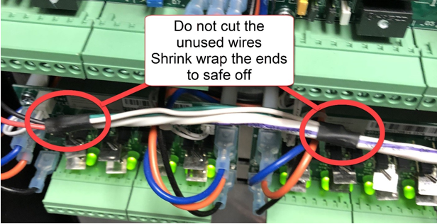
- Unused wires in a wire group that may not be currently used shall not be cut back but shrink wrapped at both ends for possible future use.
- Refer to heat shrinkable labels example and illustrations that follow.

- Project record drawings shall include documentation of all work - including the documentation of equipment, wiring, conduits, cable trays, and raceways - that are related to the work but are provided under other sections.
- Product Manufacturers
- Access control intelligent controllers, input modules, output modules, and card readers shall be branded by Lenel and use Lenel part numbers. No substitutions are acceptable.
- Other equipment shall be produced by the manufacturer or manufacturers indicated herein. No substitutions are acceptable.
- All equipment shall be the most recent updated production version.
- Provide PO# from the vendor of supplier used to purchase card readers (enables warranty contact).
- Product Specifications
- Intelligent System Controller
- Microprocessor-based intelligent controller provides complete local processing of access control transactions. Can store up to 500,000 cardholders in non-volatile flash memory. Supports up to 64 card reader-controlled doors through use of card reader interface modules. On-board high-speed Ethernet 10/100Base-T upstream port for connection to central SEAC server computer. 15 MB of available on-board, non-volatile flash memory.
- Intelligent controller shall provide local processing for up to 16 different card formats, up to 32,000 access level permissions, 255 holidays, 255 time zones, and provide elevator control support for up to 128 floors.
- Provide Lenel Model #LNL-X3300. No substitutions are acceptable.
- Single-Reader Interface Module
- Card reader interface module allows monitoring and control of one card reader-controlled door. Provides one card reader input, one SPDT (Form C) output rated at five amperes, one SPDT (Form C) output rated at one ampere, two general purpose supervised inputs, and one tamper input. Connects to intelligent controller using RS-485 data connection.
- Provide Lenel Model #LNL-1300 S3. No substitutions are acceptable.
- Dual-Reader Interface Module
- Card reader interface module allows monitoring and control of two card reader-controlled door. Provides two card reader inputs, six SPDT (Form C) outputs rated at five amperes, eight general purpose supervised inputs, one power status input, and one tamper input. Connects to intelligent controller using RS-485 data connection.
- Provide Lenel Model #LNL-1320 S3. No substitutions are acceptable.
- Input Control Module
- Input control module provides 16 general purpose inputs, one power status input, and one tamper input. General purpose inputs programmable as supervised or unsupervised. Two SPDT (Form C) outputs rated at five amperes. Connects to intelligent controller using RS-485 data connection.
- Provide Lenel Model #LNL-1100 S3. No substitutions are acceptable.
- Output Control Module
- Output control module provides 16 SPDT (Form C) outputs rated at five amperes. One power status input, and one tamper input. Connects to intelligent controller using RS-485 data connection.
- Provide Lenel Model #LNL-1200 S3. No substitutions are acceptable.
- Equipment Enclosure - Large
- Large equipment enclosure for SEAC equipment, 36"H x 30"W x 4½ 6 1/2 "D. 16 Gauge steel construction with top and bottom cabinet locks. Removable back plate with mounting provisions for Lenel modules, power supplies and other equipment.
- Enclosure shall provide space for up to six Lenel modules, two power supplies, accessory modules, and standby batteries
- Provide Life Safety Power Model #E8M. No substitutions are acceptable.
- Equipment Enclosure - Small
- Small equipment enclosure for SEAC equipment, 24”H x 20W” x 4.5 61/2”D.16 Gauge steel construction with cabinet lock. Removable back plate with mounting provisions for Lenel modules and other equipment.
- Enclosure shall provide space for up to six Lenel modules.
- Provide Life Safety Power Model #E4M. No substitutions are acceptable.
- Power Supply
- Power supply for use in powering all SEAC equipment including electric lock hardware. User- selectable for 12 VDC at 20 amperes, or 24 VDC at 10 amperes. Mercury cards in the cabinet can operate 12 VDC or 24 VDC. Card readers at the door are powered by Mercury cards. All powered devices like door hardware (locks & strikes), Rex’s, PIMS, Camden CX-33, gateways and door prop alarms are to powered by 24 VDC.
- Provide label on panel with line voltage and circuit sources.
- Wiring shall be labeled.
- Provide Life-Safety Power Model #FPO150/250-2C82D8PE8M2. No substitutions are acceptable.
- All PC Tab security power supplies shall be 24V BPS-10A and individually monitor each power supply with a CT1 monitor module.
- Individually monitor each power supply with a CT2 monitor module.
- Connect power supplies to the emergency generator. If emergency power system is an NFPA compliant generator, the battery back-up shall be for 4 hours; otherwise, size batteries as required by NFPA 72 for batteries as the sole secondary source of power and for identified critical alarms requiring back-up power longer than four hours for reporting to the campus monitoring system.
- Batteries shall be minimum of two each twelve Ah Enersys/Yuasa batteries as determined by load calculations – no substitutions.
- Conduit entrance in bottom of BPS cabinets prohibited. Reserve this zone for batteries in a normal upright position.
- Strictly adhere to manufacturer’s recommendations for separation between line voltage and low voltage wiring.
- Power Distribution Module
- Power distribution module provides eight individually protected Class II power outputs rated at 2.5 amperes per output. Uses solid-state circuit breakers. Provides visual indicator for each power output.
- Provide Life Safety Power Model #D8P. No substitutions are acceptable.
- Lock Controller Module
- Lock controller module provides eight relay-controlled lock outputs. Each output may be programmed for the following modes:
- Voltage output from power supply one
- Voltage output from power supply two
- Fail-safe
- Fail-secure
- Normally open dry contact
- Normally closed dry contact
- Fire alarm interface for egress lock control
- Provide Life Safety Power Model #C8P. No substitutions are acceptable.
- Lock controller module provides eight relay-controlled lock outputs. Each output may be programmed for the following modes:
- Multi-Technology Card Reader (no keypad)
- Multi-technology access card reader that features ability to simultaneously read multiple card formats including:
- UTC ProxLiteTM and ISO ProxLite
- HID 125 kHz ProxCard II, ISOProx II, ProxKey II, and ProxCard and Corporate 1000 formats
- MIFARE ISO 14443A Card Serial Number (CSN)
- MIFARE/DESFire CSN
- Vicinity ISO 15693 CSN
- HID iCLASS CSN
- Operates at 6 to 16 VDC and supports both Wiegand and F/2F compatible communications formats. Tri-color status indicator and audible sounder
- Provide Allegion/Schlage LNL-MT15-485. No substitutions are acceptable.
- Multi-technology access card reader that features ability to simultaneously read multiple card formats including:
- Multi-Technology Card Reader With Keypad
- Multi-technology access card reader with integral PIN keypad. Reader features ability to simultaneously read multiple card formats including:
- UTC ProxLiteTM and ISO ProxLite
- HID 125 kHz ProxCard II, ISOProx II, ProxKey II, and ProxCard and Corporate 1000 formats
- MIFARE ISO 14443A Card Serial Number (CSN)
- MIFARE/DESFire CSN
- Vicinity ISO 15693 CSN
- HID iCLASS CSN
- Operates at 6 to 16 VDC and supports both Wiegand and F/2F compatible communications formats. Tri-color status indicator and audible sounder. Includes integral twelve-button numeric keypad.
- Provide Allegion/Schlage LNL-MTK15-485. No substitutions are acceptable.
- Multi-technology access card reader with integral PIN keypad. Reader features ability to simultaneously read multiple card formats including:
- Multi-Technology Card Reader – Mullion Mount
- Multi-technology access card reader that features ability to simultaneously read multiple card formats including:
- UTC ProxLiteTM and ISO ProxLite
- HID 125 kHz ProxCard II, ISOProx II, ProxKey II, and ProxCard and Corporate 1000 formats
- MIFARE ISO 14443A Card Serial Number (CSN)
- MIFARE/DESFire CSN
- Vicinity ISO 15693 CSN
- HID iCLASS CSN
- Reader shall be designed to mount on standard 1¾" and 2" wide mullions. Dimensions of reader shall not exceed 1.73" wide x 5.83" high x 1.18" deep.
- Operates at 6 to 16 VDC and supports both Wiegand and F/2F compatible communications formats.
- Tri-color status indicator and audible sounder
- Provide Allegion/Schlage LNL-MT11-. No substitutions are acceptable.
- Multi-technology access card reader that features ability to simultaneously read multiple card formats including:
- Vestibule /ADA Door Operator Sequencer
- Advanced logic relay designed to support automatic door applications.
- Camden CX-33
- All authorized credentials will only unlock the door. A separate action of pushing the power assisted door touch plate will be required.
- Request-To-Exit (Rex)
- To be a low current switch internal to the door hardware that monitors the exit device’s touchbar or lever and signals the door opening.
- Audible sounders used at designated doors
- Piezo electronic sounders will be mounted to single-gang stainless steel plate and be a 12/24 VDC operation.
- Sounder shall provide audible output of not less than 85 db when measured at three feet.
- CX-DA Camden Door Prop alarm is preferred product or equal.
- EOL Resistor Pack
- End-of-line (EOL) resistor pack with 1000-ohm supervisory resistor.
- Provide George Risk Industries Model #6644. No substitutions are acceptable.
- Wire and Cable
- Provide cabling between all SEAC equipment in accordance with manufacturer’s requirements. All cabling shall be shielded unless otherwise specified by manufacturer.
- Wire and cable shall be sized to provide minimum resistance and minimum voltage drop to the devices being supplied. Voltages delivered to all devices shall be within the tolerance specified by the device manufacturer.
- No conductor shall be smaller than #22 AWG gauge.
- Wire to electric lock hardware shall be no smaller than #16 AWG gauge unless otherwise noted.
- All wire and cable installed within ceiling plenums, air handling spaces, and cable trays shall be UL listed for such use.
- Comply with equipment manufacturer’s recommendations for wire and cable.
- Comply with all applicable code requirements.
- Composite Cable
- Plenum-rated composite cable for use between SEAC backboard and access-controlled doors (Banana Cable). Consists of the following elements:
- Group 1: 16ga 4 Conductor Unshielded
- Group 2: 22ga 4 Conductor Unshielded
- Group 3: 22ga 3 pairs Shielded
- Group 4: 22ga 2 conductor Unshielded
- Provide WSECCOMP-2849 Cable. No substitutions are acceptable.
- ADA accessible doors, current and identified as future potential, shall have cabling installed. Consists of the following elements:
- Plenum rated
- 12 Conductor twisted pair jacketed
- 22ga 7 strand bare copper
- Colors--Black, White, Red, Green, Brown, Blue, Orange, Yellow, Violet, Gray, Pink and Beige
- Part# 004394-80 or W2212C0225
- Wireless Locksets
- Wireless locksets may be used on interior doors on a case-by-case basis as approved by the SEAC Technical Maintenance Engineers. In no case shall wireless locksets be used on building exterior doors leading into common access areas.
- Wireless locksets shall be self-contained lockset units that provide stand-alone access control capability at the door. Wireless locksets shall include card reader, electric lock, door position switch, and request-to-exit device. Wireless locksets shall have the following capabilities (at a minimum):
- Self-contained processor that stores cardholder locally and provide processing of access requests at the doors.
- Battery-powered using standard AA batteries.
- Available in cylindrical lock, mortise lock, and exit device configurations.
- Provides wireless communications with wireless portal gateway using 2.4 GHz spread spectrum wireless signal with AES 128-bit encryption.
- Wireless portal gateways shall serve as interface between SEAC and wireless locksets. Wireless portal gateways shall be provided in locations as needed to reliably communicate with wireless locksets. Wireless gateway portals shall have the following capabilities at a minimum:
- Communicates to wireless locksets using 2.4 GHz spread spectrum wireless signal with AES 128-bit encryption.
- Capable of supporting from 1 to 64 wireless locksets.
- Uses 802.15.4 protocol with clear channels above 802.11 to allow interoperability with Wi-Fi.
- Connects to SEAC VLAN using 10/100/1000 Base-T bit Ethernet.
- Appears as Intelligent Controller to Lenel OnGuard software.
- Approved Manufacturer/Model Numbers (verify currently approved products with WWU project manager prior to issuing bid set) [Industry’s rapid advancement compels this concept].
- Intelligent System Controller
- Execution
- General
- Provide all labor, tools, supplies, materials, and equipment required for the design, installation, configuration, programming, and testing of a complete and operational building access control system.
- Install all equipment in accordance with manufacturer’s instructions and approved shop drawings.
- Programming sequences of equipment are to be provided (ex: power door operators) coordinated with WWU naming convention provided by WWU Technical Maintenance.
- LifeSafety Power access control cabinets shall have 25% spare point capacity and physical space for cards within a single or combined cabinet provision (confirm design with WWU Project Manager).
- Intelligent Controller Panel Installation
- Install each panel at SEAC backboards in equipment closet locations as indicated.
- Install each panel at a location and height to facilitate ease of service.
- Identify the software and hardware address of each panel with a permanent metal marking label installed on the exterior of the cabinet.
- Neatly dress and tie all wiring within panel. Do not obstruct access to terminal strips and configuration jumpers with wiring.
- Provide terminating resistor on all unused input connections.
- Label all inputs and outputs with a permanent marking label.
- Ground all shielded cables in accordance with manufacturer’s instructions.
- Trim and wrap all unused shield wires to prevent shorting or inadvertent grounding.
- Connections to Campus Network
- University will provide two data outlets at each SEAC backboard location and will provide network cabling from outlets to the nearest network switch. Data outlets shall be assigned to the SEAC virtual LAN (VLAN) and used for no other purpose.
- Contractor shall provide connections between data outlets and Intelligent Controller and power supply network interface module.
- Other types of security systems (video surveillance systems, intrusion alarm systems, etc.) shall not be connected to the SEAC VLAN.
- Power Supply Installation
- Install all system power supplies at Intelligent Controller panel backboard locations as indicated. Do not install power supplies at other locations.
- Provide adequate clearance around all power supplies to permit dissipation of heat.
- Install wiring harness between batteries and power supplies.
- Connect power fault outputs from each power supply to inputs Siga.
- Power all electric lock hardware from 24 VDC lock power supply located at equipment backboard.
- All system accessories, such as REX, card readers, door alarm horns, piezo sounders and the like shall be powered from 12 VDC power supply located at equipment backboard.
- Install label on all power supply batteries indicating the date that they were placed into service.
- 120 VAC input connections to power supplies to be provided under other sections.
- Card Reader Installation
- Securely mount all card readers using tamper-resistant fasteners.
- Card readers shall completely cover any electrical back box. Provide trim plates at locations where required.
- Completely seal openings in exterior walls for outdoor mounted card readers to make weather tight.
- Connection to Electric Lock Hardware
- Provide wiring and final connection to electric strikes, electric locks, transfer hinges, electric exit devices, and other such devices furnished under other specification sections.
- Verify operating voltage and current requirements of each piece of hardware provided. Thoroughly test all electric lock hardware for proper operation.
- Install pilot relay to control lock hardware where current requirements of hardware exceed relay contact rating of Intelligent Controller or where electrical isolation is required.
- Connection to Magnetic Contact Switches
- Provide cabling and connection to magnetic contact switches (door position switches) furnished under other sections.
- Install end-of-line resistor pack at each contact switch. Resistor pack shall not be installed at locations away from device.
- Test all contact switches for proper operation.
- Connection to Automatic Door Openers
- SEAC shall be used to sequence the operation of card reader-controlled doors that are equipped with automatic door openers. Door opener actuator buttons shall be connected as inputs to a SEAC input control module, and the door operator activation signal shall be connected to an output on a SEAC output control module.
- Provide cabling and connections between electric lock hardware, automatic door openers, and door actuator buttons as indicated.
- Configure SEAC software as needed to establish desired sequence of operation including timing. Touchplate activation is required to operate the door.
- Coordinate work with installer of automatic door openers.
- Connection to Elevators
- Coordinate installation of access control system for elevator with elevator installer.
- Coordinate requirements for conductors in elevator traveling cables with elevator installer. Verify that conductor quantities and types are suitable for use with card reader.
- Provide card readers to elevator installer for installation in elevator. Provide information on how to properly install and connect reader.
- Provide interface cabling between access control system and elevator control equipment. Route cabling in elevator machine room to locations designated by elevator installer.
- With cooperation and assistance of elevator installer, fully test all elevator control functions. Provide assistance to elevator installer as required to troubleshoot any elevator control related problems.
- Device Wiring, General
- Comply with manufacturer recommendations concerning the installation of wiring and cable. Observe cable distance limitations as outlined by manufacturers.
- The distance of cabling used for equipment at doors (card readers, door hardware, REX door contacts, etc.) shall not exceed 330' or 100m.
- Use standard and consistent wire conductor color-coding for device wiring. Use the same colors for each function throughout the project; for example, red and black-colored wires are always used for power; green and yellow-colored wires for detection circuit, etc.
- Install end-of-line resistor pack at detection device. Resistor pack shall not be installed at locations away from device.
- Provide separate conduits and raceways for SEAC cabling. Do not mix SEAC cabling with power wiring or with the cabling of other systems that may cause electrical interference.
- Raceways shall be in 1" conduit to each device.
- Programming and Configuration CX-33
- Contractor shall provide initial programming and configuration of the access control system. This shall include configuration of existing host computer software as necessary to accommodate addition of this building to the campus system.
- Programming shall include defining doors, door groups, inputs, input groups, outputs, output groups, maps, map groups, alarms, alarm groups, and other such system parameters. Input of all program data shall be by Contractor. Contractor shall consult with WWU project manager to determine operating parameters.
- General
Latest update
2023-11-06