
Division 32 - Irrigation Systems
- This information provides guidelines for irrigation systems. Temporary facilities and controls are covered in other parts of these standards or are available from the WWU project representative.
- WWU project representative, Facilities Maintenance (FM), the Public Safety Office, Outdoor Maintenance, and the Environmental Health and Safety Office shall approve selection of irrigation systems means and methods. Unless otherwise approved, the design intent requires means and methods that provide minimal disruption to adjacent building activities and operations.
- Coordinate locations of access boxes, valves, and irrigation controllers with project representative and Outdoor Maintenance.
- When working adjacent to occupied buildings, require means and methods that protect occupants from exposure to noise, dust, traffic, and other hazards.
- Ensure that Outdoor Maintenance reviews design development and construction documents.
- Record Drawings:
- Indicate two dimensions for all valves (including quick couplers and drain valves), stub-outs, mainline T’s, L’s and ends.
- Dimension mainline pipes and wire runs at the beginning, mid-point, and end of each curve or at each change of direction, or at 25' intervals along the curve if longer than 50'.
- Electrical:
- Wire splices shall be watertight with either 3M-Scott’s Lock Seal Tack 3576-77-78 or Pen Tite PVC Socket and Sealing Plug, Rain Bird PT-100 series.
- Valve wiring color coded as follows:
- Red wires – lawns.
- Green wires – drip.
- Yellow or purple wires – shrubs.
- Black wires – master valve.
- No splices permitted between junction boxes.
- Control wiring:
- Fasten conductors together at 2' intervals. Bundle fastened mainline at 5' intervals with plastic handcuff type of fastener.
- Run one unconnected spare control wire from the controller through each intermediate control valve box.
- Minimum size of wire number 14.
- Control wires shall be color coded as follows:
- Common wire – white.
- Lead-in wire – black.
- Extra wire – orange.
- Install detector tape or copper wire on top of PVC main line for future line detection search.
- Wire:
- Copper, ASTM B-3, #14 minimum.
- PE-39 cable from controller to flow sensor must be a single, un-spliced length.
- Two yellow AWG #12 control wires from controller to normally open master valve must be a single, un-spliced length each.
- Blue tracer wire AWG #14 along the entire mainline from the controller.
- Connectors: King Innovation 20111 Single Low Voltage Waterproof Wire Connectors
- Irrigation controller:
- Rain Bird (no substitutions: extension of existing system). ESP type with 120-V single phase service and NEMA approved stainless steel enclosure with locking cover. Confer with Outdoor Maintenance for locations, detailed specification of controller functions, number of stations and other details.
- Each controller station shall have an adjustable time setting from five minutes or less to at least one hour on a 14-day variable cycle. Controls shall allow any position to be operated manually either on or off. Install exterior controller wiring that is above ground in Schedule 80 PVC conduit.
- Manufacturers known to be acceptable for valve covers and boxes:
- Double-check valves: Carson 1730-12-3PL green in color.
- Automatic control valves: Carson 1719-13, T-Lid, one valve per box, green in color.
- Quick coupler: Carson 910-12, T-Lid, green in color.
- Conduit and Fittings:
- Under ground: Plastic, Class III, and Federal Specification W-C-1094.
- Above ground: Aluminum, Federal Specification WW-G-540.
- All interior conduits shall be metallic.
- Automatic Control Wire:
- Low-voltage control wires shall be 14-gauge wire installed under mainline and tape to pipe every 10'. Provide 2 feet loops at all directional changes and at each valve box.
- Provide conduits as necessary when turning corners or going through walls.
- Bundle wire together at 5' intervals with plastic tape or similar.
- Install secure and plumb.
- Install wire in continuous runs with no splices.
- If splices are FS approved, make all splices in a valve box and note these on record drawings and provide an extra coil of each wire at each splice to allow for contraction of wire due to temperature or settlement of backfill.
- Control wiring:
- Backflow preventer: Provide per City code and Western requirements. Double check valve assembly with the following:
- FEBCO model 850 only per standards below:
- Internally spring-loaded isolation valves, 2 ball valves and 4 field test cocks.
- All check valve internal parts to be easily accessible from top of device without removing check valve body from the line.
- Double check valves (or equivalent).
- Assembly to be rated 175 psi working pressure.
- Washed gravel under assembly to provide adequate drainage.
- Size to be same as pipe or larger.
- Electric remote-control valves: Rainbird PEB series (or equivalent)
- Quick coupling valves: Rain Bird 44LRC.
- Master valves: Rainbird GB-R Series same size as mainline
- Manual control gate valves:
- Use USA manufactured valves, resilient seat gate valves.
- 125 PSI cold-water-rated, construction to be brass or bronze on 2" and under sizes.
- Automatic remote-control valves:
- Shall be normally closed, electric solenoid operated with a maximum rating of 6.5 watts and 24 volts AC power.
- Valves shall be pressure rated 150 psi, heavy-duty brass body/bonnet with flow control stem and a manual internal and external bleed capability.
- Control wire shall be insulated single strand copper for 24 to 50 volts, and UL approved for underground installation.
- Manual valves:
- Brass angle type with hex brass union, pressure rated at 150 psi.
- Drain valves for main line to be manually operated brass straight valve.
- Access boxes:
- Valve boxes shall not be located in turf areas. NO EXCEPTIONS.
- Valve boxes shall be minimum 1" below turf grade, level and set in line or perpendicular to nearest hardscape line.
- Valve boxes shall have minimum of 6" pea gravel placed in box below valve bottom.
- For automatic valves and master valve use plastic box with bolt down cover. Box and lid green. Provide extension for adequate clearance to operate service and maintain the valve.
- Manual drain valves and ball valves shall use 10" diameter by 10" minimum box. Ground green.
- Quick coupler valves shall use Carson Model 708, 6" diameter black plastic box with green lid.
- Quick coupling valves:
- Two-piece valve, heavy-duty brass construction with stainless steel internal valve spring and locking rubber cover.
- Pressure reducing valves:
- Brass body, pressure rating 300 psi. Pressure range 25-75 psi adjustable.
- Factory pressure set at 50 psi.
- Valve covers and boxes Installation:
- Set all valve boxes at grade of lawn or shrub mulch surface.
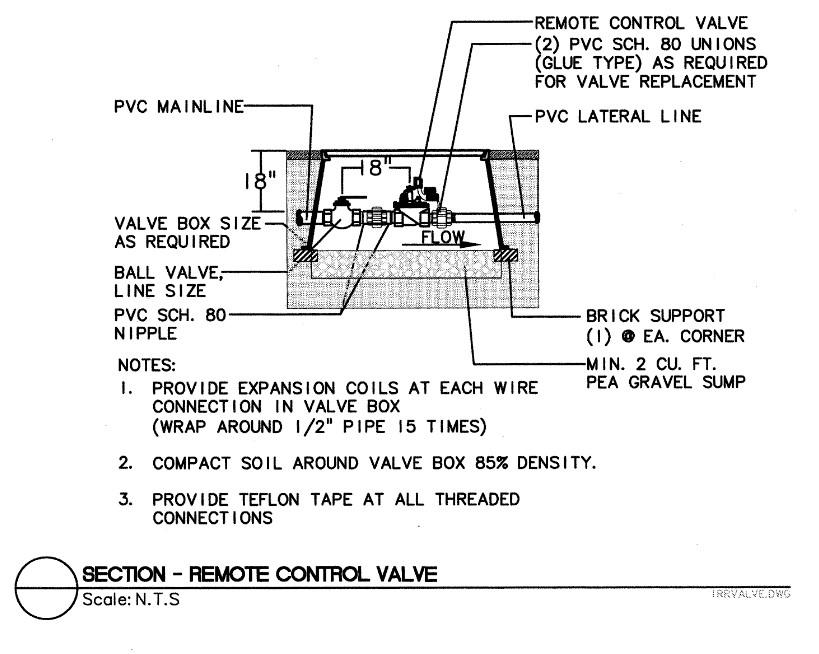
- Ensure 48" of wire are coiled around ½" pipe in box.
- 1" minimum clearance from any pipe.
- All valve boxes are to be double stacked.
- Automatic valves:
- Locate valve boxes 12" from and perpendicular to walk edges, buildings, and walls.
- Provide 12" between boxes where valves are grouped together.
- Label control line wire at each valve with a 2½" x 2 ¾" polyurethane ID tag, indicating identification number of valve (controller and station number). Attach label to control wire.
- Coil common and lead wires inside valve boxes, 2'0" minimum at ½" coils.
- Drain valves:
- Enclose in 2" galvanized steel or schedule 40 PVC pipe with locking cap.
- Provide gravel sump dry well of 2 cubic feet, 12" diameter by 2'-0" deep gravel, provide washed sand.
- See below for Detail 1: Remote Control Valve
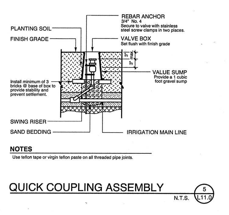
- Quick-Coupling Valve Assembly:
- Install plumb in valve box, with top of valve set 3" below top of box and grade.
- Open crushed rock in valve box to 4" below top of valve.
- Support quick coupler by attaching an 18" #4 rebar with 2 stainless steel clamps on each side.
- See below for Detail 2: Quick Coupling Assembly
- FEBCO model 850 only per standards below:
- Pipe, fittings, sleeves:
- Pipe:
- Sleeves 2 times pipe size.
- Install mainlines 24" below grade. Provide sand to 12" below grade and ID (caution) tape.
- All mainline pipes to be schedule 40.
- PVC Primer: Weld on. Purple primer #31903 to be used on all glue surfaces.
- PVC Type I, NSF approved as per ASTM-D01784, D-1785, D-2242 and Product Standard 21/70, 22/70.
- Install lateral lines 18" below grade. Provide sand to 6" below grade and ID tape.
- All lateral lines are to be schedule 40 with solvent-weld connection fittings.
- Fittings:
- PVC fittings to be schedule 40, solvent-weld type.
- Teflon on all threaded joints.
- Threaded plastic pipe: Wrap joints with Teflon tape, 4 wraps.
- No pipe dope.
- No galvanized pipe or fittings may be used.
- DO NOT USE plastic saddles and flange fittings.
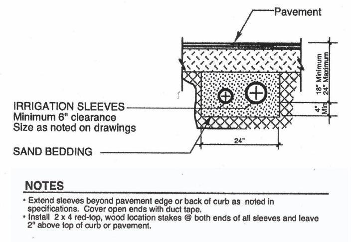
- Sleeves:
- Schedule 40 PVC pipe.
- Provide under sidewalks and other locations as selected by/with Owner to install irrigation system and allow future flexibility.
- Provide vehicle markers where sleeve ends are concealed.
- Extend sleeves a minimum of 1-foot beyond sidewalks on each side.
- Run sleeves level and perpendicular to sidewalks and pavement.
- Empty sleeves are to be marked on the sidewalk with an ‘S’ stamped in the horizontal face of the concrete.
- See below for Detail 3: Irrigation Sleeves for under hard surfaces (typ.)
- Pipe:
- Sprinkler heads:
- Pop-up type: Fixed-spray sprinkler heads, Rain Bird, 1800 series
- Spray heads shall be Rainbird 1800 series PRS SAM 4", 6",12" sizes.
- Nozzles shall be Rainbird MPR Nozzles series or Rainbird 1724 Rotary Nozzles.
- All rotor heads to be approved by FM Outdoor Maintenance Supervisor; preference Rainbird 5000+ series.
- Drip or micro-sprays to be approved by FM Outdoor Supervisor.
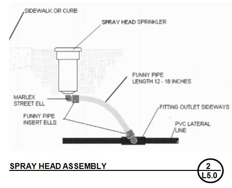
- Sprinkler head installation:
- Install all heads plumb or perpendicular to finished grade.
- Compact earth under pipe at sprinkler heads to prevent settlement from pulling sprinklers below grade.
- Install at center of symbol of drawings with the exception of the following:
- Do not install any sprinkler body that is next to a sidewalk, curb, header, etc.
- Higher than the top surface of the sidewalk or curb and leave 2-3" space from sprinkler rim to curb.
- Part circle sprinkler heads next to buildings, 12" to 18" out from the building.
- Set head elevations in existing turf, set top of sprinkler flush with top of turf mat or ½" above earth grade, whichever is highest.
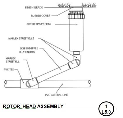
- See below for Details 4 and 5: Spray and Rotor Head Assembly
- Backfill Materials:
- Provide minimum 3 cubic foot drain rock sump at each drain.
- Provide soil tested document to Outdoor Maintenance Supervisor before WWU will accept.
- Planting areas: Native on-site soil, free of rocks and other deleterious materials. If rock or other deleterious materials are encountered, bed pipe with 4" of fill sand on all sides of pipe and/or wire.
- Paved areas: All backfill to be fill sand under paved areas.
- Drain and sump areas: Pea gravel, ¾" x ½" washed round rock.
- Construction: Prior to construction, contractor shall walk through pipe sleeve locations and depths with Outdoor Maintenance. Pipe sleeve to be a minimum of Schedule 80 PVC.
- Monuments: Carefully maintain benchmarks, monuments and other reference points. If disturbed or destroyed, replace as directed.
- Trenching or Pulling Pipe:
- Width of trench to be 1½ times the pipe’s outside diameter.
- Minimum cover depth to be:
- 18" for main lines.
- 12" for lateral lines.
- More than one pipe is permitted in the same trench:
- 2 pipes may be stacked vertically if 4" of earth separates them.
- 3 or more pipes must be laid 4" apart horizontally in trench.
- Remove any rocks or other material from the bottom of the trench that might damage pipe.
- Flush main prior to installing valves.
- After piping risers and valves are installed, but prior to installing sprinkler heads, thoroughly flush piping system under full water head. Maintain flushing until all foreign matter is removed from the line.
- Cap risers immediately after flushing.
- Pressure Tests:
- Isolate electric valves and test with a pressure pump after installing and before backfilling the mainline.
- Maintain 100 psi minimum pressure for at least 4 hours without leaks or pressure loss. Call for Landscape Architect and FS Exterior Supervisor inspection at beginning and end of this period.
- Point of Connection Assembly Installation:
- Connect irrigation system to designated irrigation meter as indicated on approved plans.
- Size piping to match size of outflow pipe from meter.
- Coordinate work with City water inspector for tests of backflow preventer prior to placing irrigation system in service.
- Install backflow preventer per detail with minimum clearances of 6" on all sides of assembly and a minimum 12" of clearance below.
- Provide 4" of drain rock at bottom of box.
- Install pressure regulator if required.
- Contractor shall be responsible for initial testing and fees associated with the testing of the backflow device.
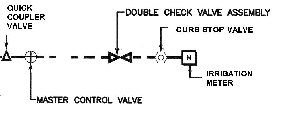
- Detail: Point of Connection Assembly: see figure 6 below.
- Irrigation Controller Installation:
- all mount controllers shall be mounted on a stable wall where applicable or for pedestal mount controllers a 12"L x 18"W x 8" deep concrete base with 4 - 1" Schedule 80 conduit sweeps provided.
- The contractor will be responsible for providing a 20-amp power service with a separate breaker.
- Low voltage wiring shall be color coded as follows:
- {} Control wire – Red
- {} Common wire – White
- {} Spare wire – Orange or Black
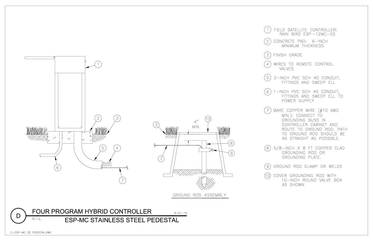
- See below for Detail 7: Irrigation Controller
- Maintenance equipment:
- Provide 2 manufacturer’s service wrenches for each head type requiring wrenches for servicing or adjustment.
- Provide 3 each of the following keys: manual drain cross handle key, valve box cover key, quick coupler key with hose swivel and controller cabinet key.
Detail 1
Detail 2
Detail 3
Detail 4
Detail 5
Detail 6
Detail 7
Latest update
2023-11-06